Getting Started With the Arduino SPE Shield
This tutorial will give you an overview of the core features of the SPE Shield.
Learn how to establish Single Pair Ethernet (SPE) communication using the Arduino® UNO SPE Shield, enabling Industrial IoT (IIoT) connectivity with minimal wiring complexity.
Overview
The Arduino® UNO SPE Shield brings industrial-grade Single Pair Ethernet (10BASE-T1S) as well as RS-485 connectivity to Arduino boards, revolutionizing how we connect devices in industrial and IoT applications. This shield combines the simplicity of Ethernet communication with the efficiency of using just a single twisted pair of wires, making it ideal for environments where cable reduction and reliable communication are crucial while still allowing for legacy devices to be part of your network with the option of RS-485.
In this guide, you'll learn how to set up your first SPE network, understand the fundamentals of 10BASE-T1S communication, and implement both point-to-point and multidrop network configurations.
Hardware and Software Requirements
Hardware Requirements
- Arduino® UNO SPE Shield
- Arduino® UNO R4 WiFi or any other UNO form factor board.
- USB cables for programming
- Twisted pair cable for SPE connection
Software Requirements
- Arduino IDE 2.0 or Arduino Web Editor
- Arduino_10BASE_T1S library (available through Library Manager)
- ArduinoModbus library (for industrial protocols)
Product Overview
The Arduino UNO SPE Shield is a versatile solution for industrial communication, IoT, and automation, combining Single Pair Ethernet (10BASE-T1S) and RS-485. It enables integration into low-power Ethernet networks and robust serial communication systems, ensuring efficient connectivity in embedded environments.
Compatible with the Arduino UNO form factor, it supports SPI, UART, and I2C, facilitating interoperability with various devices. Additionally, it features screw terminals for additional connectivity and power options. Its robust design and advanced protection makes it ideal for applications in industrial environments for remote monitoring and automated control.
Key Features
- Single Pair Ethernet: 10BASE-T1S standard with 10 Mbps data rate, supporting up to 25 meters in multidrop topology with up to 8 nodes
- RS-485 Communication: Half-duplex operation at 20 Mbps with 120Ω termination jumper and fail-safe biasing
- Multiple Interfaces: UART, SPI, and I2C connectivity through Arduino UNO headers
- Robust Design: Operating temperature range -40°C to +85°C with advanced protection features
- Dimensions: Standard Arduino shield form factor at 68.58 mm x 53.34 mm
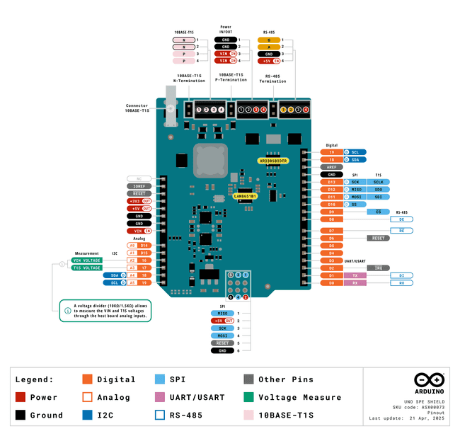
Pinout
The full pinout is available below:
Datasheet
The complete datasheet is available and downloadable as PDF from the link below:
Schematics
The complete schematics are available and downloadable as PDF from the link below:
STEP Files
The complete STEP files are available and downloadable from the link below:
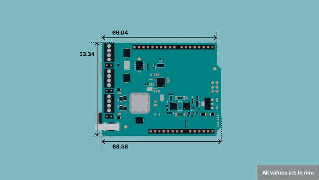
Form Factor
The Arduino UNO SPE Shield follows the standard Arduino UNO shield form factor, ensuring compatibility with all Arduino UNO boards and enabling stackable designs. With dimensions of 68.58 mm x 53.34 mm, the shield maintains the familiar Arduino ecosystem layout while adding industrial-grade communication capabilities.
The shield features the standard Arduino UNO header arrangement with digital and analog pin access, ICSP connector placement, and proper mounting hole alignment.
This standardized form factor allows seamless integration into existing Arduino UNO projects and ensures that the shield can be easily incorporated into enclosures and mounting systems designed for the Arduino UNO ecosystem.
Connectors
The Arduino UNO SPE Shield features several connectors for establishing communication and providing power.
Single Pair Ethernet (SPE)
The shield offers two primary ways to connect to a Single Pair Ethernet (SPE) 10BASE-T1S network:
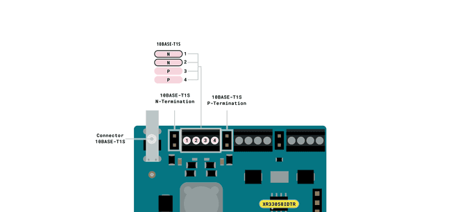
- T1S Connector: The shield includes a dedicated connector for robust, direct SPE connections to compatible devices.
- Screw Terminals: Screw terminals marked for N (Negative) and P (Positive) pins are also available.
Key Features:
- Speed: Operates at 10 Mbps under the 10BASE-T1S standard.
- Maximum Distance: Supports up to 25 meters in multidrop topology (multiple nodes on a single segment).
- Topology: Allows up to eight nodes in a multidrop network.
RS-485
- The shield exposes the RS-485 connections marked as A and B, with both GND and +5V through a dedicated screw terminal.

RS-485 Connector
Key Features:
- Speed: Up to 20 Mbps for short distances (<15 m).
- Maximum Distance: Supports up to 1,200 m with reduced speeds.
- Topology: Works in a bus topology, supporting up to 80 nodes.
Power
A screw connector for powering the board and Shield assembly is provided with two positions for GND and two for VIN (7.0 to 24.0 V).
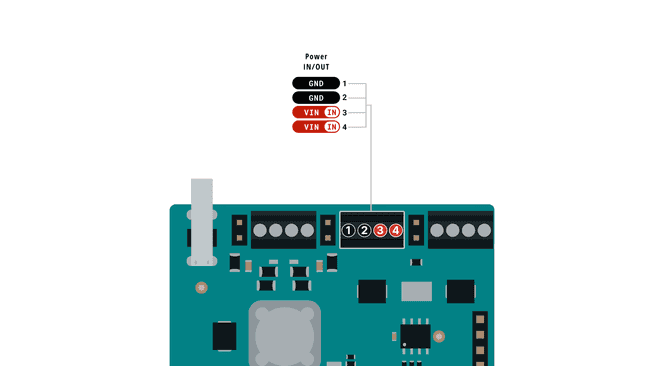
Note: The UNO SPE Shield can safely operate with a 24 VDC power supply. While the Arduino UNO R4 is designed to handle this voltage without issue, caution is advised, 24 V can potentially damage UNO R3 boards or any third-party UNO-compatible board.
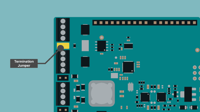
Termination Jumpers:
SPE Termination Jumper:
To enable the onboard termination resistors for the SPE bus, there are two pairs of contacts you can bridge.
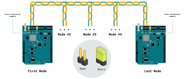
- Point-to-Point Setup: Use jumpers to enable the termination at endpoints for proper signal integrity.
- Multidrop Setup: Terminations are disabled internally; only the furthest nodes in the network should be terminated.
RS-485 Termination Jumper:
The same principle applies to the RS-485 connector however in this case there is only a single jumper that needs to be bridged.
First Use of the UNO SPE Shield
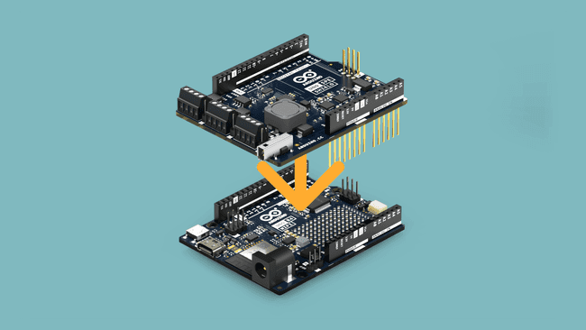
Stack the Shield
- Align the Arduino UNO SPE Shield with your Arduino board
- Carefully press down on the headers to ensure proper connection
- Verify all pins are properly seated
Power the Board
The shield can be powered through multiple sources:
- A - USB Power: Via the host board USB connection.
- B - Power Jack: Via the host board power jack.
- C - External Power: Through the VIN screw terminal (7.0 to 24.0 V). Note: The UNO SPE Shield can safely operate with a 24 VDC power supply. While the Arduino UNO R4 is designed to handle this voltage without issue, caution is advised, 24 V can potentially damage UNO R3 boards or any third-party UNO-compatible board.
- D - Power over Data Line (PoDL): Through the T1SP screw terminal or dedicated connector.
Simple Broadcast Example
This example demonstrates a simple broadcast communication system between multiple nodes on an SPE network. Each node can broadcast messages to all other nodes, and automatically responds with "pong" when it receives a "ping" message. This creates an interactive network where you can test connectivity and response times between different devices.
Hardware Setup
- Configure Termination Jumpers: For point-to-point connections, close the termination jumpers on both shields
- Connect the SPE Cable: Wire the twisted pair between the two shields' SPE screw terminals or using a T1S dedicated cable.
- Power Both Systems: Ensure both Arduino boards are powered
Sketch
The system uses UDP broadcasting to send messages to all nodes simultaneously, making it perfect for testing your SPE network setup and verifying that all nodes are communicating properly. Each node operates independently, listening for incoming messages while also being able to send its own broadcasts.
Important: Before uploading this code to each board, you must change the
NODE_ID- First board:
MY_NODE_NUMBER = 0; - Second board:
MY_NODE_NUMBER = 1; - Third board (optional):
MY_NODE_NUMBER = 2;
Remember that any termination nodes should have the termination headers properly closed, more info on the Arduino UNO SPE Shield datasheet.
The node ID determines the device's IP address (192.168.42.100 + NODE_ID) and its position in the PLCA (Physical Layer Collision Avoidance) cycle. When you type a message in the Serial Monitor and press Enter, it's broadcast to all nodes on the network. If any node receives the word "ping", it automatically responds with "pong" to the sender.
1// Simple 10BASE-T1S Ping-Pong Network2// Each board can send messages to all others3// Automatically replies "pong" when it receives "ping"4
5#include <Arduino_10BASE_T1S.h>6#include <SPI.h>7
8// CHANGE THIS NUMBER FOR EACH BOARD (0, 1, 2, 3, etc.)9const int MY_NODE_NUMBER = 0;10
11// Network addresses (like house addresses on a street)12const IPAddress MY_IP_ADDRESS(192, 168, 42, 100 + MY_NODE_NUMBER);13const IPAddress SUBNET_MASK(255, 255, 255, 0);14const IPAddress GATEWAY_ADDRESS(192, 168, 42, 100);15const IPAddress BROADCAST_ADDRESS(192, 168, 42, 255);  // Sends to everyone16const int NETWORK_PORT = 8888;17
18// Hardware objects (think of these as your network components)19TC6::TC6_Io* networkIO = nullptr;20TC6::TC6_Arduino_10BASE_T1S* networkController = nullptr;21Arduino_10BASE_T1S_UDP* messageService = nullptr;22
23// For reading typed messages24char typedMessage[128];25int messageLength = 0;26
27void setup() {28  // Start serial communication29  Serial.begin(115200);30  delay(1000);31  32  // Show which node this is33  Serial.print("\n=== Network Node #");34  Serial.print(MY_NODE_NUMBER);35  Serial.println(" ===");36  Serial.print("My IP address: ");37  Serial.println(MY_IP_ADDRESS);38  39  // Set up the network hardware40  if (!setupNetwork()) {41    Serial.println("ERROR: Network setup failed!");42    while(1) {43      delay(1000);  // Stop here if network won't start44    }45  }46  47  Serial.println("\n✓ Ready to communicate!");48  Serial.println("Type a message and press Enter to send to everyone");49  Serial.println("I'll automatically reply 'pong' if someone sends 'ping'\n");50}51
52void loop() {53  // Keep the network running (like keeping your phone connected to WiFi)54  (*networkController).service();55  56  // Check if user typed something57  checkForTypedMessages();58  59  // Check if someone sent us a message60  checkForIncomingMessages();61  62  // Show we're still alive every 10 seconds63  showHeartbeat();64}65
66bool setupNetwork() {67  Serial.println("Setting up network hardware...");68  69  // Create the network components70  networkIO = new TC6::TC6_Io(SPI, CS_PIN, RESET_PIN, IRQ_PIN);71  networkController = new TC6::TC6_Arduino_10BASE_T1S(networkIO);72  messageService = new Arduino_10BASE_T1S_UDP();73  74  // Set up interrupt (this lets the network chip tell us when data arrives)75  pinMode(IRQ_PIN, INPUT_PULLUP);76  attachInterrupt(digitalPinToInterrupt(IRQ_PIN), []() {77    if (networkIO) (*networkIO).onInterrupt();78  }, FALLING);79  80  // Start the low-level network interface81  if (!(*networkIO).begin()) {82    Serial.println("Failed to start network interface");83    return false;84  }85  86  // Create unique network identity87  MacAddress myMacAddress = MacAddress::create_from_uid();88  T1SPlcaSettings plcaSettings(MY_NODE_NUMBER);89  T1SMacSettings macSettings;90  91  // Connect to the network with our address92  if (!(*networkController).begin(MY_IP_ADDRESS, SUBNET_MASK, GATEWAY_ADDRESS, 93                                myMacAddress, plcaSettings, macSettings)) {94    Serial.println("Failed to join network");95    return false;96  }97  98  // Configure output pins (not used in this simple example)99  (*networkController).digitalWrite(TC6::DIO::A0, false);100  (*networkController).digitalWrite(TC6::DIO::A1, false);101  102  // Start the message service103  if (!(*messageService).begin(NETWORK_PORT)) {104    Serial.println("Failed to start message service");105    return false;106  }107  108  Serial.print("Network ID (MAC): ");109  Serial.println(myMacAddress);110  Serial.println("✓ Network setup complete");111  112  return true;113}114
115void checkForTypedMessages() {116  // Read characters as user types117  while (Serial.available()) {118    char newChar = Serial.read();119    120    // If user pressed Enter, send the message121    if (newChar == '\n' || newChar == '\r') {122      if (messageLength > 0) {123        typedMessage[messageLength] = '\0';  // End the string124        sendMessageToEveryone(typedMessage);125        messageLength = 0;  // Reset for next message126      }127    }128    // Add character to our message (if there's room)129    else if (messageLength < sizeof(typedMessage) - 1) {130      typedMessage[messageLength] = newChar;131      messageLength++;132    }133  }134}135
136void sendMessageToEveryone(const char* message) {137  // Don't send empty messages138  if (!messageService || strlen(message) == 0) {139    return;140  }141  142  // Send to broadcast address (everyone on network gets it)143  (*messageService).beginPacket(BROADCAST_ADDRESS, NETWORK_PORT);144  (*messageService).write((const uint8_t*)message, strlen(message));145  (*messageService).endPacket();146  147  Serial.print("📤 Sent to all: ");148  Serial.println(message);149}150
151void checkForIncomingMessages() {152  // See if a message arrived153  int messageSize = (*messageService).parsePacket();154  155  // No message or message too big156  if (messageSize <= 0 || messageSize >= 256) {157    return;158  }159  160  // Read the message161  char receivedMessage[256] = {0};162  IPAddress senderAddress = (*messageService).remoteIP();163  164  int bytesRead = (*messageService).read((uint8_t*)receivedMessage, 165                                       min(messageSize, 255));166  if (bytesRead <= 0) {167    return;168  }169  170  receivedMessage[bytesRead] = '\0';  // End the string properly171  172  // Show who sent what173  Serial.print("📥 From ");174  Serial.print(senderAddress);175  Serial.print(": ");176  Serial.println(receivedMessage);177  178  // If someone sent "ping", automatically reply "pong"179  if (strcmp(receivedMessage, "ping") == 0) {180    // Small delay to avoid message collisions (each node waits different time)181    delay(10 + (MY_NODE_NUMBER * 5));182    replyPongTo(senderAddress);183  }184}185
186void replyPongTo(IPAddress targetAddress) {187  // Send "pong" back to whoever sent "ping"188  (*messageService).beginPacket(targetAddress, NETWORK_PORT);189  (*messageService).write((const uint8_t*)"pong", 4);190  (*messageService).endPacket();191  192  Serial.println("🏓 Auto-replied: pong");193}194
195void showHeartbeat() {196  static unsigned long lastHeartbeat = 0;197  198  // Every 10 seconds, show we're still running199  if (millis() - lastHeartbeat > 10000) {200    lastHeartbeat = millis();201    Serial.println("💓 [System running normally]");202  }203}
SPI/RS-485 Network Example
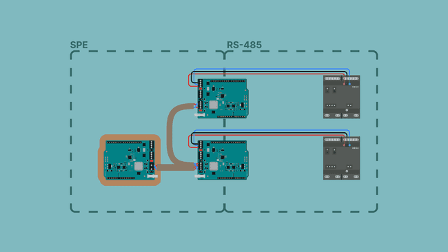
This example demonstrates a hierarchical control system where a central SPE controller manages multiple Arduino Opta boards through gateway nodes. The system uses SPE (Single Pair Ethernet) for the main network backbone and RS-485 for connecting to end devices, combining the benefits of modern Ethernet with the reliability of industrial serial communication.
The architecture consists of three layers: a central control node that issues commands, gateway nodes that translate between SPE and RS-485 protocols, and Opta boards that execute the actual control operations. This design allows for scalable industrial automation where multiple Opta boards can be distributed across a facility while being managed from a single control point.
Central Control Node (Server)
The central control node (Node 7) acts as the command center of the system, sending LED control commands to specific Opta boards through their associated gateway nodes. Operating on the SPE network, this node provides a simple serial interface where operators can type commands like "LED 3" to toggle the LEDs on remote Optas.
1// SPE Server Node 7 - Sends LED commands2#include <Arduino_10BASE_T1S.h>3#include <SPI.h>4
5const uint8_t MY_ID = 7;6
7IPAddress myIP(192, 168, 42, 107);8IPAddress netmask(255, 255, 255, 0);9IPAddress gateway(192, 168, 42, 100);10
11TC6::TC6_Io* io;12TC6::TC6_Arduino_10BASE_T1S* network;13Arduino_10BASE_T1S_UDP* udp;14
15void setup() {16  Serial.begin(115200);17  delay(1000);18  19  Serial.println("\nSPE LED Control Server");20  Serial.println("Type: LED 0, LED 1, etc.\n");21  22  io = new TC6::TC6_Io(SPI, CS_PIN, RESET_PIN, IRQ_PIN);23  network = new TC6::TC6_Arduino_10BASE_T1S(io);24  udp = new Arduino_10BASE_T1S_UDP();25  26  pinMode(IRQ_PIN, INPUT_PULLUP);27  attachInterrupt(digitalPinToInterrupt(IRQ_PIN), []() {28    io->onInterrupt();29  }, FALLING);30  31  io->begin();32  33  MacAddress mac = MacAddress::create_from_uid();34  T1SPlcaSettings plca(MY_ID);35  T1SMacSettings mac_settings;36  37  network->begin(myIP, netmask, gateway, mac, plca, mac_settings);38  network->digitalWrite(TC6::DIO::A0, false);39  network->digitalWrite(TC6::DIO::A1, false);40  41  udp->begin(8888);42  43  Serial.println("Ready!");44}45
46void loop() {47  network->service();48  49  if (Serial.available()) {50    String cmd = Serial.readStringUntil('\n');51    cmd.trim();52    cmd.toUpperCase();53    54    if (cmd.startsWith("LED ")) {55      int node = cmd.substring(4).toInt();56      IPAddress targetIP(192, 168, 42, 100 + node);57      58      udp->beginPacket(targetIP, 8888);59      udp->print(cmd);60      udp->endPacket();61      62      Serial.print("Sent to node ");63      Serial.println(node);64    }65  }66}
Transducer Node SPE/RS-485
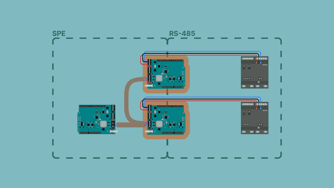
The gateway nodes serve as protocol translators between the SPE network and RS-485 devices. Each gateway consists of an Arduino board with an SPE shield, where the board's hardware serial port (Serial1) connects to the RS-485 transceiver on the shield. These nodes receive UDP packets from the SPE network, extract the command data, and forward it to the RS-485 bus.
1// SPE/RS-485 Gateway2#include <Arduino_10BASE_T1S.h>3#include <SPI.h>4
5const uint8_t MY_ID = 0;  // Change for each gateway6
7IPAddress myIP(192, 168, 42, 100 + MY_ID);8IPAddress netmask(255, 255, 255, 0);9IPAddress gateway(192, 168, 42, 100);10
11TC6::TC6_Io* io;12TC6::TC6_Arduino_10BASE_T1S* network;13Arduino_10BASE_T1S_UDP* udp;14
15void setup() {16  Serial.begin(115200);17  Serial1.begin(9600);18  delay(1000);19  20  Serial.print("\nGateway Node ");21  Serial.println(MY_ID);22  23  pinMode(7, OUTPUT);  // RS485_DE24  pinMode(8, OUTPUT);  // RS485_RE25  digitalWrite(7, HIGH);26  digitalWrite(8, HIGH);27  28  io = new TC6::TC6_Io(SPI, CS_PIN, RESET_PIN, IRQ_PIN);29  network = new TC6::TC6_Arduino_10BASE_T1S(io);30  udp = new Arduino_10BASE_T1S_UDP();31  32  pinMode(IRQ_PIN, INPUT_PULLUP);33  attachInterrupt(digitalPinToInterrupt(IRQ_PIN), []() {34    io->onInterrupt();35  }, FALLING);36  37  io->begin();38  39  MacAddress mac = MacAddress::create_from_uid();40  T1SPlcaSettings plca(MY_ID);41  T1SMacSettings mac_settings;42  43  network->begin(myIP, netmask, gateway, mac, plca, mac_settings);44  network->digitalWrite(TC6::DIO::A0, false);45  network->digitalWrite(TC6::DIO::A1, false);46  47  udp->begin(8888);48  49  Serial.println("Ready!");50}51
52void loop() {53  network->service();54  55  if (udp->parsePacket()) {56    char buffer[64] = {0};57    udp->read((byte*)buffer, 63);58    59    String cmd = String(buffer);60    cmd.trim();61    62    if (cmd == "LED " + String(MY_ID)) {63      Serial1.println("T");64      Serial1.flush();65      Serial.println("Toggle sent");66    }67  }68}
Opta RS-485 Interface
The Arduino Opta boards represent the end devices in this system, receiving commands via RS-485 and executing the requested actions.
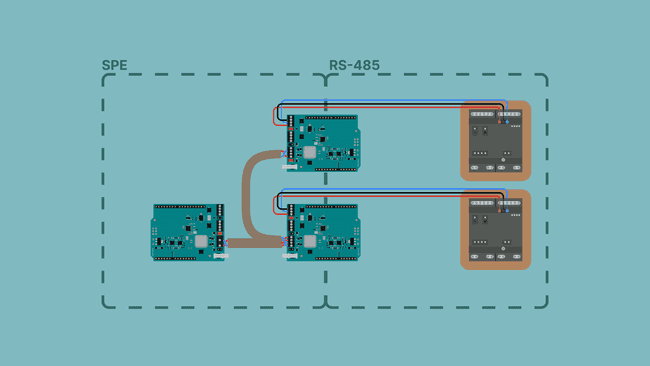
When an Opta receives a command, it parses the instruction, performs the requested operation. This simple protocol allows the central SPE controller to remotely monitor and control multiple Opta boards across the RS-485 network, creating a flexible and scalable system.
1// Arduino Opta - Toggles built-in LED on command2#include <ArduinoRS485.h>3
4bool ledState = false;5
6void setup() {7  Serial.begin(115200);  // USB debug8  delay(2000);9  10  Serial.println("\n=== Opta LED Controller ===");11  Serial.println("Toggles built-in LED on command");12  13  // Initialize RS-485 with delays14  RS485.begin(9600);15  RS485.setDelays(1000, 1000);  // Pre and post delays in microseconds16  RS485.receive();  // Set to receive mode17  18  // Setup built-in LED19  pinMode(LED_BUILTIN, OUTPUT);20  digitalWrite(LED_BUILTIN, LOW);21  22  // Flash LED to show ready23  for (int i = 0; i < 3; i++) {24    digitalWrite(LED_BUILTIN, HIGH);25    delay(200);26    digitalWrite(LED_BUILTIN, LOW);27    delay(200);28  }29  30  Serial.println("Ready for commands!");31}32
33void loop() {34  // Read RS-485 character by character35  while (RS485.available()) {36    char c = RS485.read();37    38    // 0xDE = toggle39    if ((byte)c == 0xDE) {40      Serial.println("LED Toggle - received");41      ledState = !ledState;42      digitalWrite(LED_BUILTIN, ledState);43    }44  }45}
Troubleshooting
Common Issues and Solutions
No Communication
- Verify termination jumpers are correctly set (closed for P2P, only endpoints for multidrop)
- Check cable connections and polarity
- Ensure twisted pair cable is used
Intermittent Communication
- Reduce cable length (maximum 25 m)
- Check for proper grounding
- Verify stub lengths in multidrop (< 5 cm)
Power Issues
- When using PoDL, ensure power supply can provide sufficient current
- Check voltage levels are within specification (7/24 VDC)
- Verify Arduino board voltage compatibility
LED Indicators
The shield provides status LEDs for diagnostics:
- PWR: Power status
- SPE: Link activity
- TX/RX: Data transmission indicators
Summary
In this guide, you've learned how to:
- Set up the Arduino UNO SPE Shield for Single Pair Ethernet communication
- Implement point-to-point and multidrop network configurations
- Use Power over Data Line for remote device powering
- Bridge industrial protocols like RS-485 over SPE
- Troubleshoot common connectivity issues
The Arduino UNO SPE Shield opens up new possibilities for industrial IoT applications, providing reliable, cost-effective communication with minimal wiring requirements.
Next Steps
- Explore the Arduino_10BASE_T1S library documentation
- Learn about RS-485 communication with the same shield
- Build industrial IoT projects with Arduino Cloud
- Implement advanced protocols like Modbus over SPE
Suggest changes
The content on docs.arduino.cc is facilitated through a public GitHub repository. If you see anything wrong, you can edit this page here.
License
The Arduino documentation is licensed under the Creative Commons Attribution-Share Alike 4.0 license.